R36S and R36H Rumble Motor (Vibration)

Installing a vibration motor in an R36S isn’t that hard, and most likely the easiest mod you can install in your R36S. And there are already many tutorials, both written and in video format for this. Although many of those tutorials often skip installing a very important component (more about this later). Installing Rumble in an R36H isn’t always as easy as it is for the R36S though, however; for the earlier models of the R36H (like my first Purple R36H) it is actually easier than the installing it in the R36S units because the component which is missing in the R36S is actually present in these units (again, more about this soon).
TIP: I ALSO HAVE A YOUTUBE VIDEO WHICH COVERS THE SAME AS THIS POST: Installing Rumble Into the R36S and R36H
SMALL WARNING/DISCLAIMER:
This tutorial (like many/ALL of my tutorials) is intended for REAL R36S and R36H units! Especially for the R36S there are many clones out there, and I just can’t keep up with those, and to be very honest: I don’t even want to. Some are quite good, others are extremely limited (either in performance or storage capabilities etc). I ONLY use real R36S and R36H units. So it MIGHT be possible it works on your device if you have a clone, but I can’t guarantee this. And of course, as always for all my tutorials, ‘hacks’ etc: Use at your own risk! And please: Do NOT ask me things like “how do I install this in my clone R36S/K36/R36SX or what ever other names they have come up with“. Because the answer is very simple: I. don’t. know. I don’t have any of those units, haven’t investigated them, and thus also was not able to test in person how it works. Which also means I refuse to give ‘mod tips’ on things I can’t confirm (which would only increase the risk of you breaking your device due to me giving ‘guessed connections/solutions’, which is something I don’t do).
Installing Rumble in the earlier R36H models [HL-R36H-V20 (2024-05-18)]
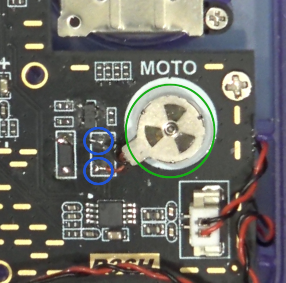
One of the absolute easiest to install the rumble into is the earlier R36H models (for me this was board version: HL-R36H-V20 (2024-05-18). It was literally as illustrated on the left here.
I salvaged an vibration motor (circled in green) from an old broken Android tablet, glued it onto the ‘rumble location’ and then soldered the two wires to the unused pads (both circled in blue on the left), and voilà! That was all there was needed to get it working. No additional components, no diodes to install or whatever. Booted into the first game I could come up with which has rumble (Raptor dos game) and yup, it works as expected (well hoped😂).
Small disclaimer: I do NOT know if this is the same for all R36H units with the same board version! Since these ‘China devices’ can be quite inconsistent (as you’ll about to learn soon). But I can guarantee you that it is not that easy for newer versions of the R36H (V21 etc). We will however get to that after we’ve covered the R36S units.
Installing Rumble in the R36S units (all)
Again, small disclaimer: I have A LOT 😂 of R36S and R36H units, and while this applies to ALL my R36S units, it’s no guarantee that this also applies to yours (even if it has the same board version printed on it!). This is due to the inconsistent nature of the manufacturers of these ‘Bulk Produced China devices’
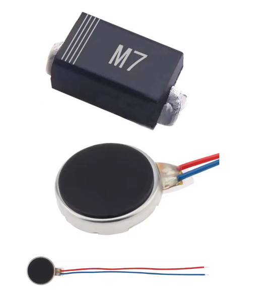
For all my R36S units it was still fairly simple to install the Rumble Motor. Most of you will most likely recognize the vibration motor shown on the left here (once as closeup and once in full with it’s wires).
That is just a simple coin-cell vibration motor of 3.7Volts with a size of 10mm by 2.7mm.
The other component is actually the crucially important component which many other tutorials tend to skip! Here I’m using an diode marked with M7. This is a diode which is quite a ‘bit’ overkill for this use (both in size and specs) but it will do. Basically any SMD schottky or rectifier diode should be fine for this purpose though, I just happen to have the M7’s in stock as my ‘main go-to’ for random projects (it’s my general purpose diode so to speak).
Why is this component sooo important you might ask? I will try to keep this as simple as possible, but when you apply power to a motor it will power the coils of the motor so that it starts spinning (due to the magnetic fields caused by this). When you however remove that power supply, those magnetic fields will instantly collapse, and this could (will) cause a (high-voltage) spike in the opposite direction. This can (and will eventually!) kill your transistor, and in worst case even the chip controlling it (which is in the R36 units the MAIN CPU (RK3326)!!
So we’ll need a diode which will ‘guide that current’ it into a safe path (simply put: circulating through the motor) until it’s ‘gone’ (dissipated).
(The location where the diode (my M7) goes)
And yes! I’m VERY aware that many (WAY TOO MANY! if you ask me!) tutorials show installing the rumble motor without this diode, and that it appears to work “fine”. And yours might also appear (emphasis on APPEAR!) to work just fine. But what you’re basically doing without installing this diode is whacking your transistor and possibly the CPU with a “huge” voltage spike EVERY time the rumble motor stops. Aka: Russian Roulette Rumble Motor Edition!
A simplified more relatable analogy to ‘non electronics users’ would be that you take a medium-hard hollow PVC bat, and with ‘gentle force’ whack the screen of your tablet.
– Hey! It survived! See! it can easily handle that… Now keep doing that over… and over.. and over.. There is a VERY real chance that you will suddenly reach a point where it cracks the screen. Either due to the ‘repeated abuse’, or due to you accidentally hitting it a bit harder once (compare this with a higher spike during motor stop).
Side note: the ‘will kill’ might be a bit dramatic, because it (the transistor) might survive a long time IF you’re lucky. But it will still kill it (eventually). It’s basically systematic abusing the transistor without the diode!
So where should I then in stall that diode??
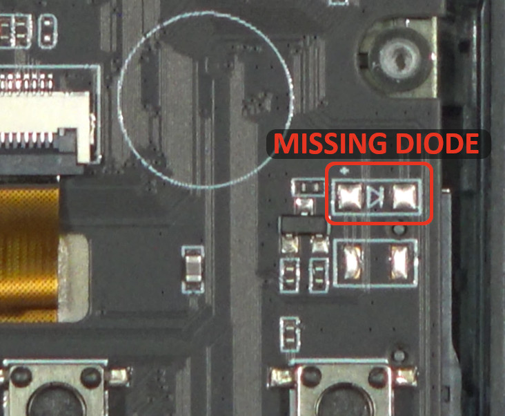
Well at the indicated location which I already marked as ‘Missing Diode’ in the previous illustration/photo😉.
If we take a look at the right illustration/photo here, you can see I’ve installed my M7 diode with the Cathode (–) marking (the stripes) to the right.
After installing the diode you can just install (solder) the two wires of your vibration motor to the two ‘silver pads’ below the diode. For most vibration motors polarity doesn’t really matter. I often just solder the blue wire (-) to the right pad, and the red (+) to the left pad here.
And that is basically all there is to properly install the rumble motor in an R36S (as mentioned earlier: at least it was for all my R36S units).
The Problem – Rumble in later/newer R36H Models (HL-R36H-V21)
But euhm.. dude!? You said that for the R36H units you don’t need additional components like the diode (for the R36S)? So why this section then?
Well that is where we get to the ‘China Devices Are Inconsistent Issue’. Because when I received my first ‘newer board’ R36H which was marked with HL-R36H-V21 (2024-11-18), I thought: let’s quickly install the rumble motor and move on…
WRONG! Because when I turned on the (new) R36H, the rumble motor also instantly turned on and did not stop vibrating at all. It started at boot and keep vibrating until turning the unit off.
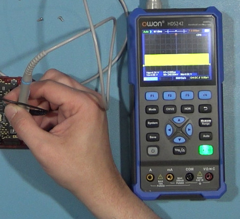
I had tried all kinds of things: replacing the transistor (with same model thinking it was defective), refitting/re-flowing the resistors around the transistor (thinking that maybe the pull-down resistor wasn’t working properly), but nothing seemed to work. So I decided to start measuring with my oscilloscope (do note that I by now had more than just one of these newer units, so i could also test in unmodified models). And when I started measuring I noticed that the newer board (V21) does not completely pull the signal low (thus resulting in the motor constantly vibrating).
The Components
So obviously, the next first logical step was to compare all components from both units (near the rumble motor that is). But strangely enough, every component is exactly the same on the V20 vs the V21 board (again: near the rumble motor).
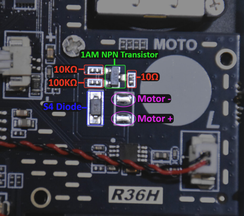
– We have a 10k series resistor going to the base of the 1AM transistor
– We have a 100K pull-down resistor connected between the 10K and the Base of the 1AM
– A 10Ω ohm current limiting resistor between the the transistor and the rumble motor
– And of course the S4 flyback diode to ‘divert’ the earlier mentioned ‘spikes’ from the rumble motor when it turns off.
An interesting thing to note here is that with all (my) RS36S units the 100K resistor is (depending on the board) actually an 22K to 24K resistor 🤔 (this is important and we’ll get back to this).
Okay, nice 👍🏽! so we now know all components used for the Rumble motor🥳. BUT! we still have the problem of the R36H turning into a constantly vibrating device, despite the components being the same!

So why does this happen?
Might it be different boot (dtb) files? With for example slightly different settings or initialization for the PWM (pulse-width-modulation)? Nope that’s 100% impossible (for my devices). Why? Because I can just swap out my SD card between the V20 and V21 unit and they will both boot and run perfectly fine (both have same Panel 4 display). HOWEVER the V21 unit DOES then constantly vibrate while the V20 does NOT with the same boot files/SD-Card. Okay okay, so could it technically be something which we could potentially solve in the dtb? And would that mean we would need another set of DTB’s just for these devices and then keep making sure EACH unit has the correct one just for the rumble motor to work? No…no … and NOOO! Not going to do that! First of because it’s not just a dtb issue, but most likely an PCB/Components issue/change.
The fact that the same SD-Card with the exact same boot files DOES make one unit constantly vibrate and it doesn’t do it for the other one, is a very clear indication that they have changed something else on the board. It can’t be a different pin configuration/assignment, because rumble in games DOES still work on both. And secondly, for the RK3326 (the CPU in your R36) you can’t just randomly re-assign a completely different functions to a pin like with an FPGA (for the more technical ones among us: yes I know! it’s a bit more nuanced, but it does NOT work like that for how the rumble is used here with PWM).
It VERY most likely means they either changed or removed a pull-down or series resistor elsewhere in the circuit, OR that they for example use a different power source (regulator/line) for the rumble motor compared to the V20 boards. Does it have something to do with the 100K resistor (which seems to be a 22K to 24K resistor in the R36S units)? Well partially, and it could be the solution for some units.
Do I know the EXACT reason it happens? No, and I won’t even remotely pretend I know why it does that in board V21 vs board V20. Have you even taken a look at those boards and how many traces, layers and other tiny components it has😉? I’m just NOT going to dig all the way through that entire board to EXACTLY reverse engineer how the damn rumble circuit works😂. I have better and more important things to do, plus I’m married and tend to keep it that way😂👍🏽. It’s just a rumble motor, not a life support device.
But no worries! I have a working solution for this, without needing to mess with your boot files. But I will briefly touch on this topic (modified boot files) because there are some ‘solutions’ circulating the internet which claim to be this exact ‘fix’!
The WRONG solution – Rumble in later/newer R36H Models (HL-R36H-V21)
There is a “solution” floating on the internet which has a custom setting in the dtb (boot files) which lowers one of the 3.3Volt regulators to 1.8Volts. Euhm… Do you have ANY clue why it’s called a 3.3 Volts (THREE! point THREE! Volts!) regulator🤔🤦🏽♀️? YES! Because it NEEDS to be a 3.3Volts regulator. In ‘defense’ of that “solution” though: In some locations where I found a ‘copied variant’ of it, it was mentioned that the (re?)poster stated: “Well, I don’t know if it affects anything else, but my unit does seem to work just fine and it stops the unwanted rumble“.
Yeah, it does indeed stop the unwanted rumble, you’ve lowered the entire voltage by half! This however does not mean that the actual signal is now properly pulled down! It just means that you’ve lowered the voltage so far that either the motor needs a stronger signal to turn on via the transistor, or that the motor is still activated, but gets much less voltage so it won’t start spinning (but DOES get current through it’s coils!). But I would not be publishing this if I hadn’t tested this (a bit) myself: It DOES (obviously) affect more than just the rumble motor!
I’ve measured a significant voltage drop near several crucial components like for example the (unsoldered) Wifi pads (which are also used for USB data port). I will admit though that I did not thoroughly checked everything it could have affected for three primary reasons:
A: I personally just find it an absolute stupid idea to just blindly turn down the voltage of one of the regulators by half on an SoC board!
B: I didn’t possibly wanted to ruin parts of my board (or even the RK3326/RK817) by under-volting it for too long for a ridiculous test.
C: Undervolting an 3.3V regulator isn’t a proper fix to begin with to ‘solve’ an issue where a signal isn’t properly pulled-down.
Following the circuit traces though, it seems it would for example also affect the audio amplifier IC’s (which seem to be on/near the same supply path as the rumble circuit).
My advice: DO. NOT. LOWER THE VOLTAGE of the 3.3V regulator to “fix” the constantly vibrating rumble motor!
The Correct solution (Explanation first)
After doing several tests, I found a much more viable “solution” (which I won’t even call a true solution, but a workaround). The TRUE solution would obviously be to completely reverse engineer the entire rumble circuit and properly use (or ‘fix’) it. But like mentioned before: That’s (for me at least) just way to much work to do for something unimportant as a rumble motor. But my solution/workaround is in my opinion a much better solution than lowering the voltage regulator voltage.
That does however require two additional components (just one if you’re lucky), and some additional soldering (nothing too serious though).
So what do you need to build rumble in the the V21 R36H units?
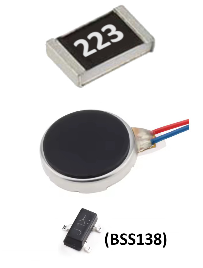
Of course the (same) rumble motor (3.7V 10mm) and if you’re lucky you only need a 22K resistor of size 0805 to work around this problem. But for most R36H units you would also need to replace the 1AM transistor with an BSS138, but more about that soon.
Why? because in my opinion the most logical way to work around this issue, is changing the voltage divider (the ‘resistor network) which controls the base of the transistor (simply put the signal which turns the transistor on and off).
Yup, this sounds all quite technical, but I will try to explain this as simple as possible.
The series resistor (the 10K resistor in the illustration above) is to ensure that the signal from the CPU (RK3326) is “severely” current limited (preventing damage to the the I/O pin of the RK3326). The 100K resistor is a much ‘heavier’ (as in higher resistance) resistor which is used as ‘pull-down’ resistor. This resistor basically provides a ‘weak pull’ towards ground for the base of the transistor. This pull-down resistor ensures that the transistor is turned off if there is no signal coming from the CPU (via the 10K resistor). And because the pull-down is a high resistance resistor, the current via the 10K resistor only has to increase just slightly to already activate the transistor and thus the rumble motor.
How does the 100K Pull-down resistor work
I know, this will take some extra time to explain, but considering my platforms are about actually teaching how things work in simple terms, I will explain how this fix works, without you just blindly installing it without understand what it actually does. if you don’t care, you can of course just skip to the next section (at your own risk😉).
I will try to explain (in simple terms) how that pull-down resistor works, however, due to the way resistance/conductivity and voltage dividers work, it might sound a bit ‘inverted’ in the following explanation but I’m guessing you will understand once you’ve read it.
Imagine the Transistor as a lever-wall-switch (lever down = rumble off, lever up = rumble on)….
Imagine the 100K resistor as a 100grams weight which is tied to the lever-switch, dangling down keeping it in the ‘off position’.
And imagine the 10K resistor as being you pulling the lever-switch upwards (on position) with a string.
With a ‘pull-down-weight’ of just 100grams, you obviously don’t really have to pull that hard to turn the switch on.
And thus because this 100K resistor doesn’t really provide that much “pull-down force“, the signal on the ’10k wire/trace’ doesn’t have to be that strong either. Which also means that IF the signal isn’t pulled down enough elsewhere, or that if there is some interference, that it will be very easy to actually (unintentionally) activate the rumble motor.
If we would now remove the 100K resistor and replace it with a 22K resistor, it will have LESS resistance to ground (pull-down), and thus be significantly stronger, and thus also require a much stronger signal via the 10K resistor path to turn on the rumble motor.
In this example you can consider the 22K resistor as a 22Kilograms weight hanging from your wall-lever-switch. As you can imagine, you would now need to put in significantly more effort to pull the switch into the on position via your string.
I know it might sound a bit confusing due to the weights vs resistance explanation (lower number being more ‘weight’), but I’m guessing most will by now understand that less resistance (22k) to ground (low), will require a stronger (higher) signal value via the 10K resistor to ‘fight’ the ‘pull-down’.
But won’t this cause more ‘”leak” voltage/current’ via the now stronger pull-down?
Ah, that is indeed something which those doing a bit more with electronics (Arduino’s, Raspberry’s etc) might wonder. And technically it’s not called ‘leak current‘ btw, but we’re keeping it simple for this topic😉. So: Yes in theory it does indeed cause (a bit) more ‘leakage current’ when it’s being pulled up, or even when it’s in idle. However! If we take into account that nearly all basic switch (and sensor) circuits use a 10K pull-down resistor, and that that barely (to not) affects the power consumption (or battery life) of those Arduino projects, you can safely assume that this replacement resistor will not affect your battery life in any meaningful way either😊.
With some limited measurements I’ve did, I observed an increase of about 25 µA (MICRO amps!) when the motor is active (vs the 100k pull-down) and an increase of about 110µA in the ‘off position’ with the 22K pull-down resistor. These differences are absolutely negligible on battery consumption. To explain it as simple as possible: Running a black-and-white GameBoy game vs a color GameBoy Color game would use “significantly” more battery than the difference this ‘resistor swap’ would cause (and that difference of those two games isn’t even really noticeable to be honest, but used as ‘simplified example’).
Small disclaimer: I only did a brief single check on these measured stats, because in my opinion and experience these values should not cause any issues, and considering I already spent waaaay too much time on a stupid thing like a 10mm rumble motor by now🤦🏽♀️, I could not be bothered to spend even more time measuring those values😂. So if you re-test this extensively your results might vary (which could also be slightly different per board btw!)
Building Rumble Into newer R36H Units Correctly (HL-R36H-V21) (Lucky Solution)
This is the ‘if you’re lucky situation‘ where you only have to replace the 100K resistor (this for me worked for two of my R36H units perfectly fine). My 13 other units this did NOT worked as ‘the solution’ (and I will cover those next).
Since I already covered most of the theory – and thus the how and why – in the sections above, I assume that I can now jump into the replacement/fix for the rumble without having to explain everything into detail too much😊. So I will keep this section brief with basic instructions and an illustration to clarify these instructions a bit more.
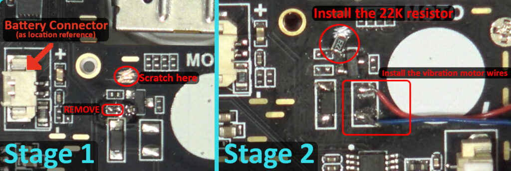
The steps to implement this ‘rumble motor fix’ for the newer R36H units are:
1. Carefully remove the 100K pull-down resistor.
2. Carefully remove/scratch a bit of silkscreen next to the transistor so that you expose the ground underneath it, at such a distance that you can install the new 0805 sized resistor. To remove/scratch the silkscreen and expose the copper underneath, you can use something like sharp tweezers or a hobby knife. Just make sure you don’t ‘dig too deep’ into the board (not cutting through the copper layer).
3. Apply some solder to the newly exposed copper
4. Now install the 0805 sized 22K resistor with one side to the transistor and the other side connected to your ‘new ground pad’
5. Install the rumble motor by soldering the two wires to the two (previously) unused pads (polarity doesn’t matter).
6. (Not illustrated) Now make sure you glue/stick the rumble motor to the white pad/location intended for the rumble motor
TIP: IF you can work with the extremely small resistors (0402), you can also use an smaller one and install it at the same location as the 100K resistor after removing it. But considering that that is most likely a bit too difficult for most which will do this modification, I decided to go with 0805, which is still quite doable for most. However that does of course require ‘creating the new pad‘ by scratching the PCB (exposing the copper).
Don’t want (or dare) to scratch the PCB?
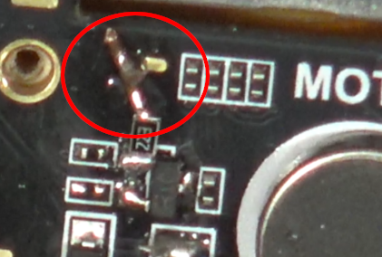
Instead of scratching the PCB, you could however also use a piece of wire to connect the other side of resistor the an already exposed ground pad of the board which I did for my orange unit like shown in the photo on the left here. Doesn’t really matter which route you take though, both will work equally well. I initially did it with scratching the PCB, which is also why this tutorial is based on that.
And that’s basically it for the newer “if you’re lucky” R36H V21 units where the rumble can be fixed by just replacing one resistor 😊.
TIP: This is also covered in the next section, but some boards seem to require an even slightly stronger pull-down resistor instead of the 22K and for those I used an 18K resistor (or an 10K + 8.2K in series to ground if you don’t have an 18K).
Building Rumble Into newer R36H Units Correctly (HL-R36H-V21) (Full Solution)
With most other V21 units (at least that is the case for all my other units) you most likely have an “extra bit of bad luck“, and then just replacing the resistor won’t work. So what happens if you have this “extra bit of bad luck“? Then your rumble motor will still keep vibrating after replacing the 100K resistor with the 22K resistor, but slightly less intense🤔.
I could have dived even further into this issue to figure out what they changed (yet again🤬) on these boards, but as you might be able to understand: I kinda had it with finding out that I had to rewrite my entire tutorial AGAIN (just like with the last one about the wifi🤦🏽♀️).
So this time I just experimented around until I found a ‘reliable fix’ which works for all (my) units (for now).
Do note though that this ‘for al units‘ goes for about 22 units I have applied it to and confirmed it as working. This also included my own 13 units plus several units of friends in which I have implemented the exact same fix with 100% success rate. But (unfortunately) you mileage may vary due to the inconsistencies in these cheaply produced products.
The theory/explanation about this ‘full solution fix‘ is actually still quite simple, it might however be a bit more difficult/trickier for those who are less experienced with soldering (sorry, I can’t help it either though that this is necessary).
The base explanation however is quite simple, if we look at the original circuit (on the right here), then we just have to do the following:
1. Remove the 100K resistor.
2. Remove The 1AM NPN Transistor.
3. Install an BSS138 N-Channel MOSFET where the 1AM was previously installed.
4. Install an 22K pull-down resistor either in the same location as where the 100K was previously installed (although that would require a very small (0402) resistor), or install it in the same way as in the previous solution (by exposing some copper or using the ‘wire’).
But my unit still keeps vibrating a bit, you said this was the FULL solution😡!
Yeah, I know, this is possible (sorry🤷🏽♀️). I have had this with just two units, and the solution for those was instead of using a 22K resistor, that I used an 18K resistor (an even stronger pull-down). This then resolved the issue completely for those units as well. If you don’t have a 18K resistor you could also use two resistors in series (a 10K and a 8K or 8.2K).
On the left side you see (a bit blurry sorry) screen cap of a board where I installed two resistors in series (10K + 8.2K) to get 18.2K just because I was out of 18K resistors. This was needed for this particular board, but again like said before: It instantly resolved the entire issue with that board also😊. And the (only) reason I shared this ‘resistors in series solution’ is to help those who (also) might not have an 18K resistor in stock😊.
So why do some boards need the 18K instead of the 22K? Well I honestly think it isn’t the board per-say to be honest. I think it’s most likely just the batch of BSS138’s I’m using where one is a bit more sensitive than the other. It could of course also indeed just be the board which has a slightly higher ‘idle signal’, but I honestly had enough of trying to dig even deeper into this over and over. You could experiment with this yourself if desired, but for me this solution works perfectly: Rumble works and only when I expect it to, and I now have a quick solution which works for all my units😊.
But shouldn’t we just use the 18K solution ‘as default’ then instead of the 22K?
No, I would highly recommend to keep the resistor ‘as high as possible’ but at a point where you are certain that the motor absolutely doesn’t turn on when it should not. If you lower the pull-down resistor it’s resistance too much, then it will affect the rumble strength and start to waste more energy/battery. If you however increase the resistance too much, then the motor will not completely shutdown anymore and thus also drain the battery for no good reasons. It’s quite a ‘delicate‘ balance you’ll have to find. Which is why I strongly recommend the BSS138 combined with either the 22K or 18K resistor depending on your board and/or results.
“The After Photo” (After replacing the 1AM and installing a 22K pull-down)
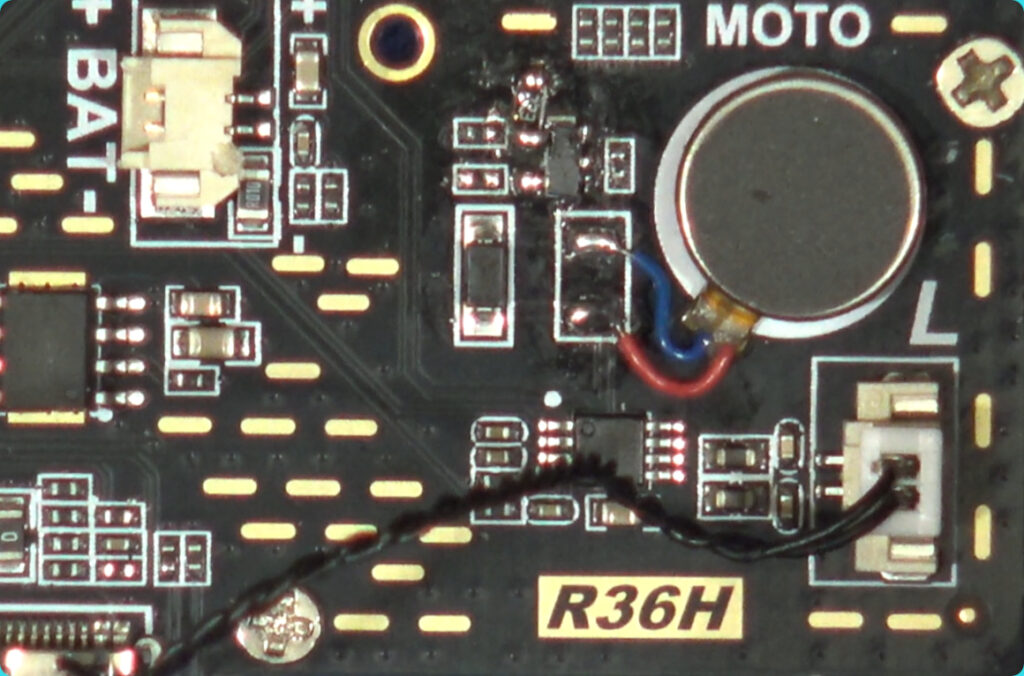
After installing the rumble motor, the 22K (0805 sized) resistor, removing the original 100K (0402 sized) in/from the R36H V21 boards and replacing the 1AM NPN with the BSS138, it should basically look like the photo on the left side (if you’ve used the ‘scratch the board technique‘).
It could of course be that they in the future change the circuit or components (yet again🤦🏽♀️) in China, and that your (even newer) R36H has problems again and thus that this solution might not help you.
In those cases I unfortunately won’t be able to help at all. Simply because I can’t (and won’t!) give a ‘working solution‘ for something I haven’t been able to test myself. However, currently this solution works for ALL my R36H units (and like mentioned earlier: I have A LOT of them 😂).

Why so specifically the BSS138?
Simple: Because that is the one I have plenty of in stock because I often use it in logic shifter circuits😂. It’s not the most ideal MOSFET for this job (which is a very technical explanation on it’s own), but that really doesn’t matter for this purpose. It works just fine and does what I expect it to do. If you have a different N-Channel MOSFET of this size with the same pinout as the BSS138? Then you can most likely use that one also as long as it’s capable of of driving the rumble motor. Just keep in mind that depending on the specs of your ‘other MOSFET’ you might need to adapt the pull-down resistor again to ensure the rumble motor turns off. Which is also why I just recommend to use the BSS138 in my tutorial because I know for a fact this combination works, and it’s easier (for the reader) to be able to just follow a ‘fixed components list’.
I will however NOT answer comments like “can I also use this or that transistor/MOSFET? because that’s the one I have in stock!“. I don’t know! I don’t know how that particular transistor/MOSFET responds with your board, the signal and your resistor network. If you have it in stock anyway? try it!😂. Just make sure the pin-out matches the 1AM/BSS138 and that it can handle the rumble motor (just stick to the specs of the 1AM for example).
Final word
That basically covers all three types of installations: All R36S units (including the flyback diode), the V20 R36H boards and the more problematic V21 R36H with the voltage divider ‘fix’ and transistor replacement to make it stop rumbling permanently. Of course I can’t (and won’t) guarantee this will work on all units or potentially new units in the future, but I can guarantee you that it does work for all my units which ranged from 3 variants of the R36S (A Panel 0 model, a panel 1 model and a panel 4 model), 2 V20 R36H units and for about 22 R36H V21 units in total😊. So I’m fairly certain that this will work for a lot of other people also (assuming they are using the real R36 units that is of course!).
Like mentioned a couple of times already, but I do want (need) to emphasize on this, because even if I state in my other tutorials that it’s only for the real R36 units, people with clones (while knowing they are clones) often still asked things like ‘how to make this work on….‘: I don’t know!
I can’t, won’t and don’t want to “help” you. It might sound like “what the f?? 😳”. But it is NOT to be a jerk, but I just refuse to give you ‘tips’ based on random guesses because I haven’t actually tested it on the same device as you have. Giving you modification tips for devices on which I haven’t confirmed it works properly is basically me playing Russian roulette with your device! It works, it doesn’t work OR it could (permanently) damage your device due to it using a completely different pin-out, circuit etc. And while my mods are already DIY projects and use at your own risk, I Just don’t want to publish (or reply) guesses like “well maybe if you…..” and then potentially bricking your device.
I’m truly sorry that this turned into a ‘multiple possibilities’ solution instead of a single-fix-for-all units. But please believe me when I tell you that I’m most likely much much more annoyed by these variations requiring different solutions. I was hoping (and working) on making just a simple ‘quick tutorial’, and due to the inconsistencies it yet again turned into more than two months work to find a ‘reasonably easy’ and proper solution which I could put in a tutorial for you guys which almost everyone can understand and follow.
If you have however build my mod/hack into your R36S/H unit, then please leave a comment at my blog and/or YouTube video so that others can see what worked for you, and that I know the information written and published is actually useful to others😊
Thanks, and have a rumbling day😉👍🏽