R36 Extra GPIO’s Discovered!

YES! You’ve read that title correct! I’ve discovered additional GPIO’s we can use in our R36S/R36H units🥳!
TIP: I also have a video of me installing this in my R36S and in my wive her R36H (without her knowing it😂) on my YouTube here.
I know there have been quite a few people asking for it, and the answer they often get comes down to one of these three
– Well you could re-purpose the RX/TX pins??!
– You Could re-purpose the ‘unused’ Vibrator motor it’s pin!
– No there are no unused/accessible GPIO’s in the R36 units!
Well ALL of these three statements are 100% incorrect in my opinion! for several reasons:
– I actually DO use the RX/TX pins as intended (for boot loader development AND as serial port under normal runtime).
– The vibrator (rumble) motor is NOT unused, it is actually FULLY addressed and used, there just isn’t a motor connected to it in most units (but I DID modded one into my units)
And just claiming there are no accessible pins is (in my opinion) not something you should actually state or claim until you have FULLY explored, measured and tested the board yourself. Yes I know that this sounds blunt, but actually ‘copy-pasting’ (or just regurgitating) statements made by others about a board which actually DOES have several unpopulated pads, test points etc without also providing an actual source which has actually tested all these possibilities is actually holding back experiments and actual results.
Those pad (unpopulated IC’s for example) and test pads (like the RX/TX pads) are there for a reason! They do NOT just slap on IC pads and (exposed) test pads which are connected to absolutely nothing onto a board “just for funsies” 😂. The questions you however have to ask when finding such pads are:
– Are these also (still) usable after the full assembly is completed or are they only used in the factory?
– Are these pads which are not connected because it’s a single PCB design intended for multiple device types/models?
– WHY are those pads (now) unused and what do (some) of those pins/pads still DO connect to?
Those are the type of questions which WILL get you further than just a “No, there are no GPIO’s (re-)usabe, because user3565252 on forum …. said so“.
And that is exactly what I did. I had to rewrite/adapt lots of the bootfiles etc anyway while working on my custom distro (SystemR36) for these devices, and because I also already had a couple R36 units and boards of them laying around I could sacrifice IF needed, I though: Screw this, I’m just going try to see if I can get some extra GPIO’s to work.
How I did it
If you don’t care about how I discovered/searched the pins, then just skip this chapter😊 (to the Which pins I’ve discovered part) . I will however keep this part brief so I won’t kill you with boredom😂. But for those who do want to learn how to do this, I basically did the following.
first I ran: sudo cat /sys/kernel/debug/gpio
Which will give a result like this (click to collapse)
 gpio-3   (                    |cd                  ) in  lo
 gpio-11  (                    |rk817_dc_det        ) in  hi
 gpio-17  (                    |?                   ) out hi

GPIOs 32-63, platform/pinctrl, gpio1:
 gpio-34  (                    |GPIO KEY BTN-A      ) in  hi
 gpio-37  (                    |GPIO BTN-B          ) in  hi
 gpio-38  (                    |GPIO BTN-Y          ) in  hi
 gpio-39  (                    |GPIO BTN-X          ) in  hi
 gpio-44  (                    |GPIO DPAD-UP        ) in  hi
 gpio-45  (                    |GPIO DPAD-DOWN      ) in  hi
 gpio-46  (                    |GPIO DPAD-LEFT      ) in  hi
 gpio-47  (                    |GPIO DPAD-RIGHT     ) in  hi

GPIOs 64-95, platform/pinctrl, gpio2:
 gpio-64  (                    |GPIO BTN-VOLUP      ) in  hi
 gpio-65  (                    |GPIO BTN-VOLDN      ) in  hi
 gpio-66  (                    |GPIO F3             ) in  hi
 gpio-67  (                    |GPIO F4             ) in  hi
 gpio-68  (                    |GPIO F5             ) in  hi
 gpio-70  (                    |GPIO TOP-LEFT       ) in  hi
 gpio-71  (                    |GPIO TOP-RIGHT      ) in  hi
 gpio-77  (                    |sysfs               ) out lo
 gpio-86  (                    |Headphone detection ) in  hi

GPIOs 96-127, platform/pinctrl, gpio3:
 gpio-104 (                    |amux-sel-b          ) out hi
 gpio-105 (                    |GPIO F1             ) in  hi
 gpio-106 (                    |GPIO TOP-LEFT2      ) in  hi
 gpio-107 (                    |amux-sel-a          ) out hi
 gpio-108 (                    |GPIO F2             ) in  hi
 gpio-109 (                    |amux-en             ) out lo
 gpio-110 (                    |cd                  ) in  lo
 gpio-111 (                    |GPIO TOP-RIGHT2     ) in  hi
 gpio-112 (                    |reset-gpios         ) out hi

GPIOs 509-511, platform/rk805-pinctrl, rk817-gpio, can sleep:
This gives me a broad idea of the pins currently in use for things like the power led, built-in game pad etc. It will NOT show the pins for the RAM, PMIC (the RK817) etc, but no worries: Most of those we can’t (easily) “mess with” anyway since that will often just result in a “Device or resource busy” kinda error when we would try to take manual control of it.
So now I could just “randomly” start doing something like:
echo “37” | sudo tee /sys/class/gpio/export
and IF that would succeed it would just return 37 in the terminal. Then I could try something like:
echo “out” | sudo tee /sys/class/gpio/gpio37/direction
To turn the direction of that pin into output mode (note: not all pins support output mode, but this is how I went for the pins I wanted😉)
if we then again still get an out as result in the terminal (and no errors accompanied with it), then I could try to do:
echo “1” | sudo tee /sys/class/gpio/gpio37/value
To drive the pin high and:
echo “0” | sudo tee /sys/class/gpio/gpio37/value
to drive it low again.
While doing this I obviously needed a way to check IF there where pins changing from HIGH/LOW while measuring this with either a multi-meter or oscilloscope. But since I had at-least 4 pins of which I wanted to know IF they where usable GPIO’s (I had already noticed that the other four where just VCC and GND pins), it would be extremely slow to do this for DOZENS of pins. This would basically mean the following flow:
– Export a pin nr with the command
– Set the direction to out with the command
– Set it to high
– Probe each of the pins/pad I’m checking IF they are re-usable as GPIO to see if they have changed to HIGH.
And then I would also have to keep track of which pins I’ve already had (AND which ones to skip! to keep the system stable!)
You can probably imagine already that that would take A LOT of time.
So what I did to make this process A LOT faster was basically the following:
I created a simple shell script (.sh), which ran a for loop with (via variables) predefined ‘start and end numbers’ to check for a certain range, and I also made a list of ‘pins to exclude’ (which would automatically be skipped while testing).
That script would then say:
“You’re about to test pin nr: GPIO…“
“Press [ENTER] to start, [S] to skip or [ESC] to abort completely“
I could then use S to skip a pin if I noticed that I accidentally forgot to exclude a “system crucial pin”, and enter would then do the following:
– It would FIRST write to a currentpin.txt the pin number it’s going to test, AND run sync to ensure the file has actually been written!
– it would export the pin
– Put the pin in out mode
and then it would alternate the pin between HIGH/LOW with an interval of about 250ms while showing the following message:
“Alternating GPIO…, press [ENTER] to ready-up to test the next pin or [ESC] to abort the test“
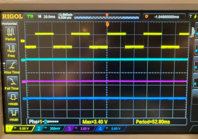
Now I could quickly poke around with my scope and just press enter to find the next process. But to speed this process up even further, I just soldered a couple wires directly to the pad I wanted to figure out and then used my 4 channel Rigol DS1054 oscilloscope hooked up to those wires to figure out which GPIO’s they where attached to. Next to this I also hooked up my OWON 2CH HDS242 oscilloscope to two other pads of which I wanted to know if those where also usable GPIO’s (they weren’t😉😂).
Now all I had to do was sit back, press enter and check the oscilloscopes to see if we suddenly saw a nice block wave appear on one of the channels 😊
Disclaimer: The photo above is a recreation quickly done with my function generator to show the effect of 4 channels active with one (the yellow one) having ‘found’ a GPIO pin which is currently actively switching between HIGH/LOW. Because I didn’t created photo’s or videos while doing this research.
|
Advertisement blocked due to cookie settings.
Please consider reading our AdSense Information page to learn why we use advertisments on our website, how you can enable them, or how you can even get rid of this 'red box' by becoming a Patreon (any tier). The AdSense Information page also explains that and how we are telling Google/AdSense to only show non personalized / non tracking advertisements. |
Why the currentpin.txt?
Ah… you’ve paid attention 😉. Well yeah you might wonder why I let the script save the current pin to a text file before starting the test on it… Well you can trust me on this one: When you are going to run through a loop with a massive amount of pins and just randomly setting them to output mode and then also like a cowboy with a blindfold toggling the trigger HIGH/LOW on a random target (pin): IT. WILL. CRASH at some point😂. There is not a question IF it will crash but WHEN it will crash😂 doing it this way. And if I have the ‘current pin which caused the crash written down’, then I can simply edit the .sh script, and make it start (resume) from the next pin after the one that ‘made it crash’.
And THAT is how I found the four additional GPIO pins which I can now use in the R36 for some extra turbo charge nerd stuff😉.
HEY! But what about that script? Where is it? Why no nice ‘click to collapse’ code block for it??
VERY SIMPLE: Because this is “the internet”, and what happens on the internet? People get lazy, people want stuff with the least possible effort and preferably even just copy-paste-it-works, without needing to understand what they are doing. And because a script like that without the proper pins being skipped for YOUR SPECIFIC device/SoC could actually lead to some very serious damage to either the SoC, the board or attached modules/peripherals. I will NOT share that script sorry (no you don’t need to leave comments to ask for it either!). I basically already explained EXACTLY what I did and how I did it. And with that information you should be able to make such a script for your specific SoC and/or board. I just find it TOO risky to put a script like that on my website ‘for grabs’, because I KNOW it will evantually result in something like “DAMN! I used your script to test my GPIO’s on [insert boardname] and now my display/wifi-module/sensor…. is toast!!!”. And if I would then reply It’s only made for the R36!, …. “Well you should have said it’s only for the RK3326/R36….”. Not falling for that trap AGAIN😉😂
DISLAIMER:
This is how I MYSELF did it, and often do it (this is also what I personally call the quick-and-dirty-way😂). It WOULD be much more appropriate to FULLY dive into the datasheets of the SoC in question, map out as much as possible beforehand (known pins), exclude those from the get-go in the eventual HIGH/LOW test etc etc. I DID actually exclude quite a few critical pins, but did NOT wanted to waste a butt-load of time just to “learn the full RK3326 pin mappings”. And I’m one of those idiots whom not just buys one or two of these devices when he gets excited and has plenty of project ideas, nope, I actually have over 20 of these units for different purposes, tests and even a couple to actually sacrifice for more comprehensive tests! So keep this VERY WELL in your mind when doing RECKLESS😂 (because that is what these ‘hacking’ methods are!) tests like these are! It COULD seriously cost you your device! So PLEASE do NOT do it this bluntly if you aren’t willing to take that risk! The pins which I have discovered ARE safe to use (IF you are using the correct device obviously😉), but I would NOT recommend beginners to just bluntly start firing a ‘shotgun’ with command to a wide range of pins😂.
NOTE: IF there are people interested in all the all the datasheets for both the RK3326 and the RK817, I will upload them (which will happen anyway with the next upcoming project(s) 🤔😉. Those contain all the “interesting data” like which pins are capable of what currents, what signals, which groups they belong to (to keep it simple) etc etc. But personally I think that for most of the target audience of THIS particular project (simply the R36), that my DTB modification information is more than enough to get you going with what you want/need to know😊.
Which pins I’ve discovered
On the R36H (and also the R36S) there is an unpopulated pad of which I found 4 usable pins which are the following pins:
| Datasheet name | GPIO Name | Functions |
|---|---|---|
| GPIO1_A0 | GPIO32 | GPIO1_A0/FLASH_D0/EMMC_D0/SFC_SIO0 |
| GPIO1_A1 | GPIO33 | GPIO1_A1/FLASH_D1/EMMC_D1/SFC_SIO1 |
| GPIO1_A4 | GPIO36 | GPIO1_A4/FLASH_D4/EMMC_D4/SFC_CSN0 |
| GPIO1_B1 | GPIO41 | GPIO1_B1/FLASH_RDY/EMMC_CLKOUT/SFC_CLK |
Notice those EMMC listings? That tells me that there possibly is an R36 variant which does have an eMMC. Ours luckily DOESN’T, because A: eMMC are CRAP😂, and B: then we would not have these awesome 4 GPIO’s to play with😂.
Do keep in mind though: KEEP THE CURRENT LOW! I mean REALLY low! I would recommend an ABSOLUTE maximum of 4mA! This will not only prevent draining your battery, but it will also keep your RK3326 alive and kicking! With my recommendation of using a low current LED with a 1K resistor (more below), you will stay well within this limit, and it will still be MORE than enough to have a clearly visible LED.
You could if you want to go full on nerd even use these pins with software driven SPI, but I’m not going to dive into that topic, because this blog post will be more than long enough already😂. I JUST wanted drive activity LEDs in my units, because that just NEEDS to be present in a device which is actually intended to run retro (for me mostly DOS and 90’s PC) games in my opinion. Back in those days? Selling a computer without an drive activity LED (often called an IDE or HDD LED back then)? That was basically a crime 😂! Heck! I even had harddrives which had LEDs built INTO them back then😂. So yes. for ME personally, my RETRO device NEEDS drive activity LED’s, period!😂
DUDE! Even more data? Where are those pins!!!?
Yes, more data! 😂 I know. But I publish all this stuff not to just hand you all my work on a ‘silver platter’ but I’m hoping I’m also ‘educating you’ on HOW I did this, what I’ve learned/discovered while testing and what to look out for. So you might also be able to contribute to project like these in the future with your own discoveries and thus keep the ball rolling😉. But no worries here are (finally) the pins and where you can actually find them in your R36H. Do note though that this is only for the HL-R36H-V21 boards and the R36S boards (ALL my R36S units had this unoccupied pad!). The R36H units with the board HL-R36H-V20 unfortunately don’t have this pad, and I might need to investigate those more deeper (since my primary development board is an V20 unfortunately).
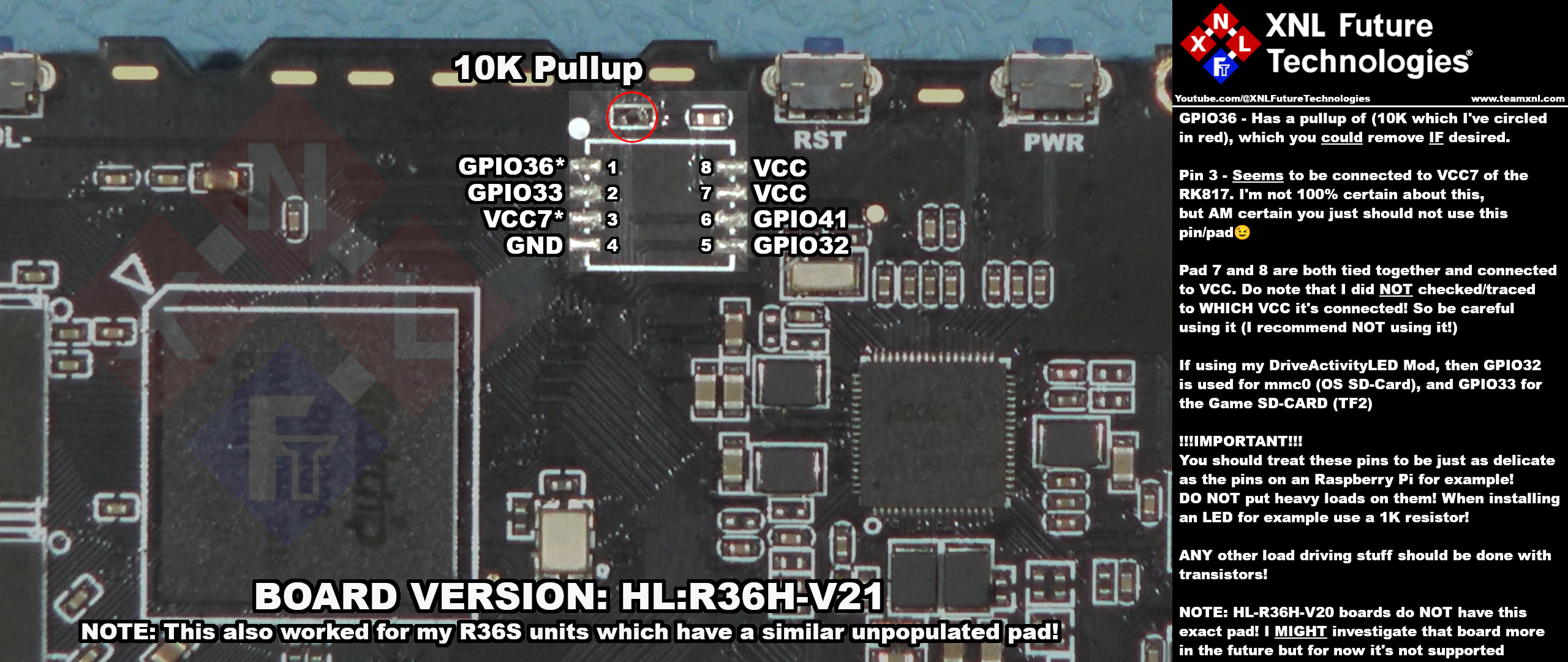
IMPORTANT NOTE FOR BEGINNERS: Do you notice the white dot at the top left of the ‘chip area’? That is the ‘pin 1 marker’. So if you have a board with a different orientation, not sure where to look at or what pin 1 is on your board, then use that ‘dot’ to identify what pin 1 is😊.
From that pin (pin 1) you always count downwards and then counterclockwise upwards again on the other-side.
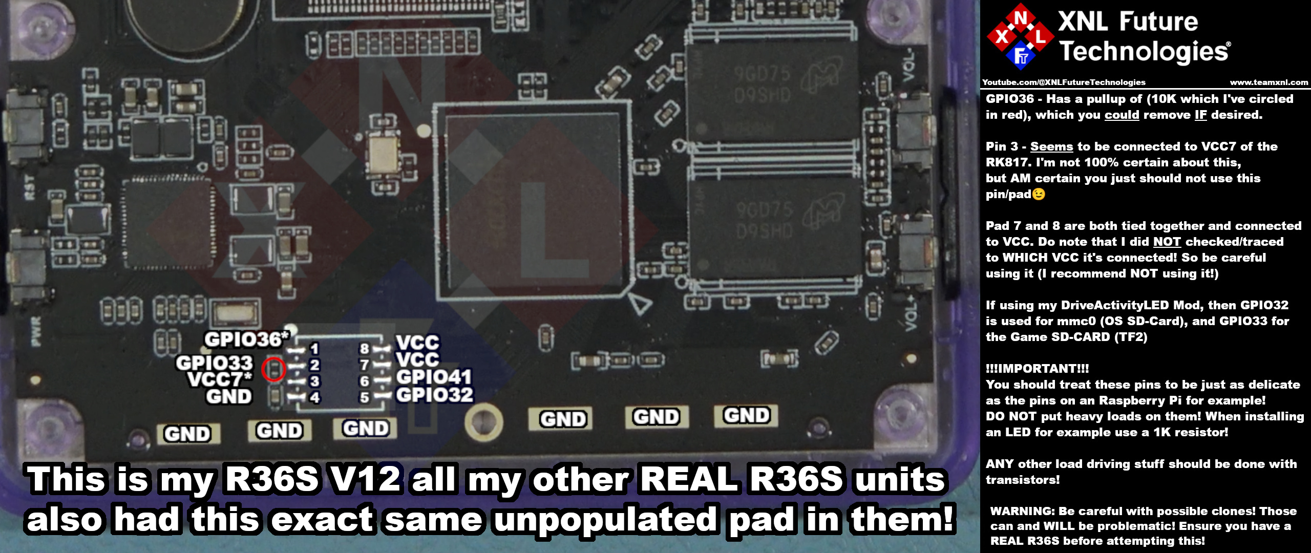
NOTE: I have confirmed this to be working on my R36S units as well! BUT PLEASE do keep in mind that the term R36S is one of the biggest ‘cash-cows’ on websites like AliExpress! There are DOZENS of clones, with a VERY poor job if imitating/ripping off the board. Some use eMMC onboard, others use a single RAM Chip, etc etc… So MAKE SURE you have a REAL R36S when attempting this on the R36S. For the R36H I’m still not aware of actual clones imitating the R36H. There ARE other variants milking the same series/family, but those do carry a different name, a larger/different screen or housing etc… But the R36H still SEEMS to be a ‘pure name’ till this day. Another thing to keep in mind is that the “socket”/pads are upside down in the R36S.
HL-R36H-V20 UPDATE: I did found another unpopulated pad on that model, but it’s NOT compatible with this mod! so ONLY for V21 R36H models!
R36S reference pinout
Just for reference I decided to also map out the pinout of the R36S for this mod
But what can I do with those pins?
This is absolutely not meant condescending in ANY way, so don’t get me wrong! But if you have to ask that question, then I personally STRONGLY recommend NOT to mess with those pins of your R36 AT ALL. But instead to first start with something like an Arduino or Raspberry Pi. Because these pins are basically exactly that (to put it simple): Unused I/O (Input/Output) pins of an Arduino/Raspberry, but then inside your R36. So for anyone having a bit of experience with those, finding unused pins in a device like this? That’s like finding the holy grail😂.
Okay, maybe not THAT important, but it’s basically “limitless”.
Again: I don’t want to make this blog post TOO long (which is already happening again😂), so I won’t deep dive into all the possibilities, but instead focus on the part of ‘activating’ the pins for use in the device tree blob, and then also setting up two of them as drive activity LED’s (one for each SD-Card).
Modifying the DTB file (ArkOS ONLY!)
This section is ONLY needed for ArkOS! DO NOT do this when you’re currently one of the few running on SystemR36, OR if you’re reading this (long) after SystemR36 has gone public and are now running the public version! This because SystemR36 has this feature built-in and it can simply be enable via a setting in GRiB (the boot menu) – I will show this further on.
NOTE: I do NOT support dArkOS, simple because I haven’t used dArkOS and don’t plan on using it myself. It MIGHT be possible you can just apply the same ‘hack’/patch to the DTB files of dArkOS but I ABSOLUTELY don’t know if it will work or not, and neither will I (try to) keep up with dArkOS! Meaning it might work now, but will stop working in the future randomly🤷🏽♀️.
Installing the required dtb tool (the sane way: On Linux😉)
If you’ve left the insanity of Windows behind you and are also running on Linux, and you’re running on an Debian/Ubuntu based distro, then you can install the required tool which is needed to decompile and recompile your DTB file (don’t freak out! it sounds more complicated than it is😉) using the following command: sudo apt install device-tree-compiler
If you’re using a different (base) distro, then just lookup the package name and package manger for your distro of course (but if you do, then you probably already know which command to use 😉).
Installing the required dtb tool (the “insane” way: On Windows😛)
On Windows you can also install the same tool and use the exact same commands I’m about to explain further on, by opening the powershell (NOT cmd/command line!) and then typing: winget install oss-winget.dtc
IMPORTANT: After installing you HAVE to close the powershell and re-open it (I don’t know why 🤷🏽♀️, Microsoft just like to restart for everything, has been like that since the 90’s😂).
DISCLAIMER: I ONLY have Windows 11 install on an external drive specifically to help you guys with these ‘tutorials’. I refuse to use Windows for ANY other task these days, so I have NOT tested it extensively, but from the two tests I did, the results are exactly the same. IF you for some reason have ANY issues using the tool I’m about to explain (dtc), then I really can’t help you with it, and you will have to resort to (other) forums, reddit etc, sorry.
Copying the DTB file from your R36 to your computer
Once you’ve installed the dtc tool, you will need to copy the .dtb file from your R36 to your computer. Do this by inserting the OS-SDCard into your pc and then copying the ‘rk3326-rg351mp-linux.dtb‘ file to your computer (NOT the ‘rg351mp-kernel.dtb’ file! which is misleadingly named to be honest, because that is the dtb used by the U-Boot system). This file can be found on the BOOT partition of our SD-Card.
NOTE: If your dtb files are named differently, then again: I can’t help you sorry. The whole ArkOS/dArkOS and custom versions for R36 units and the clones for it has became such a clusterf*ck, that I can’t keep track anymore of which dtb files etc are used by which (also the reason I decided to make my own full custom and clean R36 specific distro). If this is the case than you could most likely (NOT guaranteed) assume that you need to copy-and-modify the larger of two dtb files. There will most likely be an difference of about 30kb between the two dtb files, where the smaller one is the one used to U-Boot and the larger one for the operating system itself.
Once you’ve copied it to your pc: make ANOTHER back-up on your pc. Just in case you accidentally mess something up, then you can still revert back to the original or try again!
TIP: (Especially if you’re on Windows) make sure to copy the .dtb files to a location which are easily accessible from the terminal/command-line. While you in Linux can easily right click in basically any directory (folder) and click on “Open in terminal”, Windows most of the time doesn’t have this. So if you would then open the power shell, and you have copied it to your desktop, then you will have to do something like:
“cd c:\users\yourusername\desktop\dtbfiles“. Making a directory on for example your d drive (if you have one) like: d:\dtbfiles would make this a bit easier😉.
Decompiling the dtb (ONLY for ArkOS!)
It might sound super intimidating if you’re not programming (yet 😉), but decompiling the .dtb file is nothing more than just running one simple command 😊. For both Windows and Linux the command is exactly the same. Just make sure you first navigate (IN the Terminal/Powershell!) to the directory where your dtb file is. (On Linux you can use the command ls to confirm if it’s there, and on windows (IF in powershell!) you can also use ls or dir).
Now type the following command (again: the same for both operating systems):
dtc -I dtb -O dts -o rk3326-rg351mp-linux.dts rk3326-rg351mp-linux.dtb
IMPORTANT: Pay attention to the EXACT ORDER of the commands/arguments and the file names, I will break it down for those interested:
dtc = is the program/compiler/decompiler
-I = CAPITAL i!, meaning you are going to specify the input file (with the next argument)
dtb = The next argument for the -I part, so we’re telling dtc that we’re INPUTTING an dtb file
-O = CAPITAL o, meaning we’re going to specify the output file with the next argument
dts = The next argument for the -O part so we’re telling it that we’re going to output an dts file (from the dtb input we fed it)
-o = LOWER-CASE o! now we tell it that the next argument we’re going to give it will be the output filename
rk3326-rg351mp-linux.dts = The output filename, NOTE THE .dts at the end! VERY important!
rk3326-rg351mp-linux.dtb = The file we’re going to use as the ‘input file’, this one does have the .dtb at the end.
What is the difference between the dtb and dts? Can’t I just rename it myself🤯?
I get why you might thing that, but that tool (dtc) isn’t just renaming it. I will keep this simple, but the dtb is a DeviceTreeBlob, of if it’s more easily to remember for you (but technically incorrect naming😉): DeviceTreeBinary. Meaning it’s basically put in ‘computer giberish’ which you can’t read and/or edit without destroying the entire file after just changing one character 😉.
The dts file is the DeviceTreeSource file, this is a completely plaintext file which you can edit with something like kate, nano or tilde if on Linux (just to name a few), or with something with Notepad++. Small ‘plug here’; If you’re on Windows and not using Notepad++, then (in my opinion) YOU SHOULD😉! All the decades I was on Windows it was my go-to editor for almost anything, I can truly recommend it, especially since MS Notepad has became a bloated mess these days.
I got a WHOLE BUNCH of error/warning messages!!
Yeah, I wish I didn’t had to state it like this, but thats “completely normal”. Well it would NOT be normal if the dtb was perfectly tailored to the device, cleanly made etc. But that’s just what happens when everyone blindly copies, edits and redistributes and then rinse-repeat dtb files in the ‘Embedded Community Scene’ 😉. As long as you didn’t got a single warning like file file not found etc, then you are most likely good to go. If you did, then you are very likely not in the same directory/folder as your dtb file.
If you did got a hot mess of warnings like for example (but not limited to):
rk3326-rg351mp-linux.dts: Warning (graph_child_address): /syscon@ff140000/lvds/ports: graph node has single child node 'port@0', #address-cells/#size-cells are not necessary
rk3326-rg351mp-linux.dts: Warning (graph_child_address): /syscon@ff140000/lvds/ports/port@0: graph node has single child node 'endpoint@0', #address-cells/#size-cells are not necessary
rk3326-rg351mp-linux.dts: Warning (graph_child_address): /syscon@ff140000/rgb/ports: graph node has single child node 'port@0', #address-cells/#size-cells are not necessary
rk3326-rg351mp-linux.dts: Warning (graph_child_address): /syscon@ff140000/rgb/ports/port@0: graph node has single child node 'endpoint@0', #address-cells/#size-cells are not necessary
rk3326-rg351mp-linux.dts: Warning (graph_child_address): /dsi@ff450000/ports: graph node has single child node 'port@0', #address-cells/#size-cells are not necessary
rk3326-rg351mp-linux.dts: Warning (graph_child_address): /dsi@ff450000/ports/port@0: graph node has single child node 'endpoint@0', #address-cells/#size-cells are not necessary
Then this is, euhm… “completely normal” 😂. So you should now also have another file in the same directory but ending with .dts instead of .dtb:
rk3326-rg351mp-linux.dtb
rk3326-rg351mp-linux.dts
Editing the dts (ONLY for ArkOS!)
To edit the dts file I (personally) recommend you to use Notepad++ if you’re on Windows, and for Linux, yeah any editor depending on your desktop environment will work just fine, just don’t use Vim if you don’t want to torture yourself while having to search through the 5000+ lines of dts file 😉.
And I’m going to emphasise on this one more extra time: DO. NOT. DO. THIS. for SystemR36! if you’re already running it or if you’re doing this after the public release of it! These dtb steps (yes ALL of them) are ONLY needed for ArkOS! It will blow your brain when you get to the SystemR36 step (yes singular 😂) to do this later.
So pick your poison (the editor) and open the dts file just like you would open a plain .txt file.
But some blocks you told me to find/CTRL+F don’t seem to exist in my dts file!
I will also be very honest upfront: If you can’t find one or more the blocks I’m going to mention here… then I unfortunately CAN’T help you. The one I’ve used as example is the ‘common panel 4 dtb for the R36 on ArkOS’, but then yours is most likely not using the same dtb structure! 90% of the DTB files modified for ArkOS/The R36 are internally exactly the same with some minor changes for the display panel for other models, and here and there with an additional Fn button (for the R36S). So IF you’re using the ‘common dtb files’, then ALL these sections SHOULD be present. If that’s NOT the case, then chances are VERY likely you either have an imitation/clone R36(S), OR you are using some customized distro which uses a different layout. In that case I just can’t help you, it’s not a matter of don’t want to, I just can’t. I don’t have (or use) ANY other distro than my own these days, will be very honest and also state that I don’t WANT to download all kinds of other distro’s just to test these mods randomly. But if it’s for a different device/clone etc, I REALLY can’t help you, not even IF I would want to, because I ONLY own about 5 real R36S units and 20+ R36H units. I don’t have ANY of the others, no clones, no Pro or max models, no R40/R49 or what other kind of scams they made up to resell the SAME RK3326/specs with😂.
Fine, lets continue and assume you do have all blocks…
First we’re going to search for “gpio1@ff250000 {” (without the ” quotes), that block should look like this:
gpio1@ff250000 {
	compatible = "rockchip,gpio-bank";
	reg = <0x00 0xff250000 0x00 0x100>;
	interrupts = <0x00 0x04 0x04>;
	clocks = <0x02 0x15c>;
	gpio-controller;
	#gpio-cells = <0x02>;
	interrupt-controller;
	#interrupt-cells = <0x02>;
	phandle = <0xbf>;
};
We’ll need to add one line and four new block to this section so it will look like this (I’ve made the new lines bold here):
gpio1@ff250000 {
	compatible = "rockchip,gpio-bank";
	reg = <0x00 0xff250000 0x00 0x100>;
	interrupts = <0x00 0x04 0x04>;
	clocks = <0x02 0x15c>;
	gpio-controller;
	#gpio-cells = <0x02>;
	interrupt-controller;
	#interrupt-cells = <0x02>;
	phandle = <0xbf>;
	status = "okay";

	// GPIO1_A0 (GPIO32)
	gpio1-a0 {
		//gpio-hog;
		gpios = <0 0>;
		line-name = "led-mmc0";
	};

	// GPIO1_A1 (GPIO33) - SFC_CLK
	gpio1-a1 {
	//	gpio-hog;
		gpios = <1 0>;
		line-name = "led-mmc1";
	};

	// GPIO1_A4 (GPIO36)
	gpio1-a4 {
		gpio-hog;
		gpios = <4 0>;
		line-name = "xnl-gpio36";
	};

	// GPIO1_B1 (GPIO41)
	gpio1-b1 {
		gpio-hog;
		gpios = <9 0>;
		line-name = "xnl-gpio41";
	};
};
But I don’t want to use your stupid DriveActivityLED mod! I just want normal GPIO’s!!!
Whoa! fair shot😂! Well then just use this block instead which doesn’t prepare two of those GPIO pins to be used as an Drive Activity LED Trigger 😊 (NOTE: You will then obviously have to program them yourself if you want to do something with them from your code!). Just click on reveal universal GPIO to show the block (I’ve hidden it to keep the post a bit more manageable):
Click to reveal universal (no Drive Activity LED Trigger) GPIO ‘code block’
gpio1@ff250000 {
	compatible = "rockchip,gpio-bank";
	reg = <0x00 0xff250000 0x00 0x100>;
	interrupts = <0x00 0x04 0x04>;
	clocks = <0x02 0x15c>;
	gpio-controller;
	#gpio-cells = <0x02>;
	interrupt-controller;
	#interrupt-cells = <0x02>;
	phandle = <0xbf>;
	status = "okay";

	// GPIO1_A0 (GPIO32)
	gpio1-a0 {
		gpio-hog;
		gpios = <0 0>;
		line-name = "xnl-gpio32";
	};

	// GPIO1_A1 (GPIO33) - SFC_CLK
	gpio1-a1 {
		gpio-hog;
		gpios = <1 0>;
		line-name = "xnl-gpio33";
	};

	// GPIO1_A4 (GPIO36)
	gpio1-a4 {
		gpio-hog;
		gpios = <4 0>;
		line-name = "xnl-gpio36";
	};

	// GPIO1_B1 (GPIO41)
	gpio1-b1 {
		gpio-hog;
		gpios = <9 0>;
		line-name = "xnl-gpio41";
	};
};
Now the easiest way to explain where (about) to place the next block is by just telling you to search for: “pcfg-input {“, and then you should end up in a section of the dts file showing the pcfg-input { section followed by an i2c { section, something like this:
pcfg-input {
	input-enable;
	phandle = <0x11e>;
};

<You are going to insert the new block here>

i2c0 {
	i2c0-xfer {
		rockchip,pins = <0x00 0x08 0x01 0xb0 0x00 0x09 0x01 0xb0>;
		phandle = <0x5b>;
	};
};
You might have noticed the “<You are going to insert the new block here>“, that will (obviously😉) not be in your file, but that is where you will need to paste the following block (I have yet again also included the previous (pcfg-input {) and next (i2c0 {) sections so you can also see/ensure you don’t accidentally forget any brackets (}) or ‘line terminators’ (;). So the NEW section is yet again highlighted with bold font:
pcfg-input {
	input-enable;
	phandle = <0x11e>;
};

gpio1-sfc {
	sfc-gpio-pins {
		rockchip,pins =  <1 0 0 0xb1>,  // GPIO1_A0
				 <1 1 0 0xb1>,  // GPIO1_A1
				 <1 4 0 0xb1>,  // GPIO1_A4
				 <1 9 0 0xb1>;  // GPIO1_B1
	};
};

i2c0 {
	i2c0-xfer {
		rockchip,pins = <0x00 0x08 0x01 0xb0 0x00 0x09 0x01 0xb0>;
		phandle = <0x5b>;
	};
};
Now the last block you will need to add – but ONLY if you are following along to install the DriveActivityLED mod, otherwise you can skip this section entirely if you’re just using it to enable the GPIO pins! – will be found by searching for “gpio_leds {“. This block by default will look something like this:
gpio_leds {
	compatible = "gpio-leds";
	pinctrl-names = "led_pins";
	pinctrl-0 = <0xc0>;
	phandle = <0x150>;

	heartbeat {
		label = "blue:heartbeat";
		gpios = <0x5c 0x11 0x00>;
		linux,default-trigger = "heartbeat";
	};
};
To explain it as simple as possible, that block basically tells Linux (the kernel) which led’s it has and what to do with them by default (the default trigger). We’re going to add two block to that section, and again I have copied the entire section while highlighting the new section in bold font:
gpio_leds {
	compatible = "gpio-leds";
	pinctrl-names = "led_pins";
	pinctrl-0 = <0xc0>;
	phandle = <0x150>;

	heartbeat {
		label = "blue:heartbeat";
		gpios = <0x5c 0x11 0x00>;
		linux,default-trigger = "heartbeat";
	};

	mmc0-activity-led {
		label = "disk:mmc0";
		gpios = <0xbf 0x00 0x00>;  // GPIO1_A0 GPIO32
		linux,default-trigger = "mmc0";  // Use mmc0 for SD card 1 activity
		default-state = "off";
	};

	mmc1-activity-led {
		label = "disk:mmc1";
		gpios = <0xbf 0x01 0x00>;  // GPIO1_A1 GPIO33
		linux,default-trigger = "mmc1";  // Use mmc1 for SD card 2 activity
		default-state = "off";
	};
};
And that’s about it. Now you’ll need to save the file (CTRL+S in most editors), and you can close the editor.
Recompiling the dtb (ONLY for ArkOS!)
And as you might already have guessed it by now, this sounds alot more intimidating than it is. To do this we’llt just hop back into the Terminal/powershell, which you most likely didn’t closed yet, and if you did, then just navigate back to the same directory as where you kept your .dtb and .dts file. From the Terminal (or powershell) we’ll now need to run the command ‘inverted’. I’m not going to explain each parameter again, because they mean exactly the same, just make sure you pay A LOT! of attention to the order and what you enter where! Because running the command in the incorrect order could for example mean that you will DEcompile the dtb again into a dts, and thus it will overwrite (WITHOUT CONFIRMATION!) the file you just edited, meanign you can start all over again😉.
The command to run:
dtc -I dts -O dtb -o rk3326-rg351mp-linux.dtb rk3326-rg351mp-linux.dts
Notice that we now specified dts for -I, that we’ve specified dtb for -O and that we’ve swapped the filename.dtb and filename.dts. Make sure you got all this right!
HOLY WHACKERS!! I got A LOT more warnings now than when I decompliled!!!😳
Yup😂! but again “completely normal” with circulated dtb files like this which have been decompiled and recomiled a billion, well now a billion and one times before 😉. As long as your warning look like something like this (just a buttload more):
rk3326-rg351mp-linux.dts:1355.3-35: Warning (clocks_property): /spi@ff1d0000:clocks: cell 2 is not a phandle reference
rk3326-rg351mp-linux.dts:1372.3-35: Warning (clocks_property): /spi@ff1d8000:clocks: cell 0 is not a phandle reference
rk3326-rg351mp-linux.dts:1372.3-35: Warning (clocks_property): /spi@ff1d8000:clocks: cell 2 is not a phandle reference
rk3326-rg351mp-linux.dts:1386.3-25: Warning (clocks_property): /watchdog@ff1e0000:clocks: cell 0 is not a phandle reference
.....
/#size-cells are not necessary
rk3326-rg351mp-linux.dts:843.12-853.7: Warning (graph_child_address): /syscon@ff140000/lvds/ports/port@0: graph node has single child node 'endpoint@0', #address-cells/#size-cells are not necessary
rk3326-rg351mp-linux.dts:867.10-882.6: Warning (graph_child_address): /syscon@ff140000/rgb/ports: graph node has single child node 'port@0', #address-cells/#size-cells are not necessary
rk3326-rg351mp-linux.dts:871.12-881.7: Warning (graph_child_address): /syscon@ff140000/rgb/ports/port@0: graph node has single child node 'endpoint@0', #address-cells/#size-cells are not necessary
rk3326-rg351mp-linux.dts:2046.9-2062.5: Warning (graph_child_address): /dsi@ff450000/ports: graph node has single child node 'port@0', #address-cells/#size-cells are not necessary
rk3326-rg351mp-linux.dts:2050.11-2061.6: Warning (graph_child_address): /dsi@ff450000/ports/port@0: graph node has single child node 'endpoint@0', #address-cells/#size-cells are not necessary
And you did NOT got actual errors, then you’re good to go😊👍🏽.
Copying the newly generated/compiled .dtb to your device (ONLY for ArkOS!)
NOTE: This is the last block for the “ArkOS Only” section.
Now you’ll have to copy the newly compiled dtb file (the one which was originally in the directory should now be overwritten with your updates) back to the boot partition of your R36 it’s storage card.
WARNING: Like mentioned in the beginning: Do make sure you still keep a copy of the original file at all times!
IF anything goes wrong, you accidentally messed up the edit, your device turns out to be incompatible for some weird reason etc, you do want to be able to revert back to the original file. Even if it’s just for an retry of this mod!
|
Advertisement blocked due to cookie settings.
Please consider reading our AdSense Information page to learn why we use advertisments on our website, how you can enable them, or how you can even get rid of this 'red box' by becoming a Patreon (any tier). The AdSense Information page also explains that and how we are telling Google/AdSense to only show non personalized / non tracking advertisements. |
Enabling the DriveActivityLEDs (OR standard GPIO!) in SystemR36
SystemR36 is completely prepared for mods like these (and even comes with the “GPIO expansion mod” for the R36 by default), to enable the DriveActivityLEDs mod all you have to do is making sure your R36 is completely shutdown (off). Then follow the next simple steps:
– Turn on the R36 and while it’s booting keep holding down the R1 button, depending on if you have a login password setup or not, you will now automatically have entered GRiB or SystemR36 will ask for your user password first. No worries if you do have login password enabled, you can let go of the R1 (SystemR36 now already knows you want to go into GRiB after logging in!).
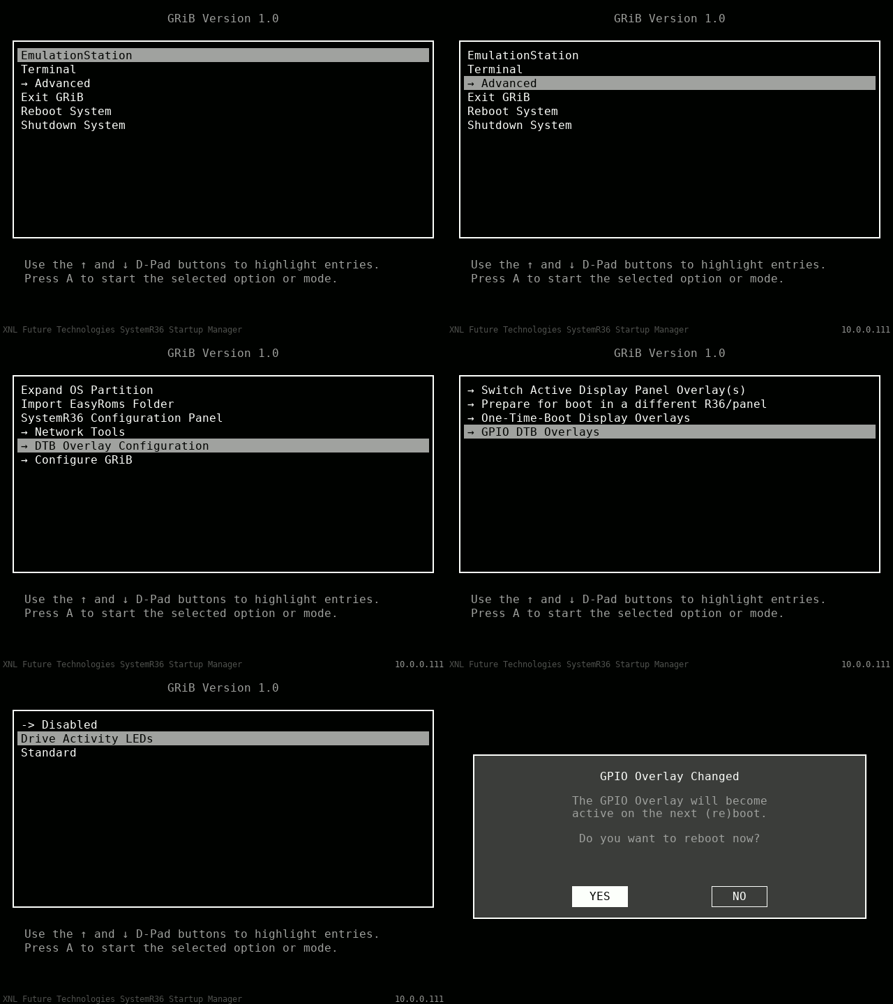
Then when in GRiB the steps to activate either the Drive Activity LEDs, the normal GPIO or even to deactivate them again are very simple. Just navigate to:
Advanced -> DTB Overlay Configuration -> GPIO DTB Overlays and then select Drive Activity LEDs.
Press A to confirm, GRiB will then ask you if you want to reboot because the overlay will become active upon next reboot, so select yes with the dpad and press A to confirm.
If you have already built in the Drive Activity LED’s previously, then they will now start working immediately while the system is (re)booting. If you haven’t built them in yet, then keep following the hardware part of this blog post below.
The hardware part of the Drive Activity LEDs
I’m going to keep this section fairly simple because I also have a full video on YouTube where I show how I did it, but the basic schematic on how to hookup the two LEDs is basically as follows:
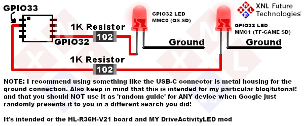
I did added a small warning in regards to this schematic showing up on Google, because this did happen in the past and then people started emailing me that a completely unrelated project didn’t worked or that it broke 🤦🏽♀️😂, but you can ignore that part for this tutorial.
As you can see, it’s actually a VERY simple hardware mod to get working with EPIC results. All you need is two components (per channel): A 1K resistor and an led in the color of your choice. If you want to do it super pretty you could go full smd with 0805 SMD’s (which I will do in the next video where I install ALL my mods at once in a factory stock unit), or you can use a 3mm led and mount it like I did in the video, which also looks (unexpectedly) quite good to be honest.
I won’t lie, I was absolutely amazed by the effect it had in the R36 of my wife I build it into as test 😂 (she didn’t knew, and as of writing this post she still doesn’t know! She will find out once she sees her R36 unit in the video we’re checking before uploading it later 😂). But I’m pretty certain she will absolutely love it and also love the fact that one of her units is the first one to receive one of my custom hacks/mods😂.
Final words
I hope this post was useful to you, I know it was to a few (since I had already noticed people on the internet asking IF there would be unused GPIO’s in the R36), but I hope this inspires more than just those few to also start tinkering with their own device and enter the amazing world of the power of embedded electronics.
Disclaimer
And as always (kinda default, but have to say this!): Doing ANY modifications (either software AND/OR hardware) is 100% at your own risk, your own responsibility and I/we will not accept any liability if your stuff breaks while doing so.
(Possible) Questions / FAQ
Calling it “frequently asked questions” on a brand new post is in my opinion a bit misleading, but it does instantly convey what this section it😉. These are however questions I do frequently get on my projects related to the R36 or the R36 units in general.
Q: Can you also make this work for dArkOS please?
A: IF your R36 used dArkOS like shown in my ArkOS installation tutorial (which I can confirm works for dArkOS also!), then it will most likely already work. IF your unit/installation uses different dtb files or for ANY other reason this mod/hack does not seem to work with your dArkOS installation, then I unfortunately can’t help you, sorry. I had absolutely zero interest in switching over to dArkOS (from ArkOS), just to end up on another partially to not supported distro for the R36 with ‘taped together fixes for the R36’. Which is exactly the reason why I decided to design a custom Linux distro specifically made FOR the R36. And thus I also do not use dArkOS at all. So sorry, I ONLY have a single card with dArkOS on it which has the sole purpose of ensuring that applications/games I’ve made FOR my own distro will also be as compatible as possible with ArkOS/dArkOS.
Q: Can’t you just make the dtb files so I can just download the correct one for my own unit (or a set of dtb files for different panels)?
A: No sorry, I can’t (and won’t). There are just too many clones out there (especially for the R36S units!), and it’s just impossible for me to ‘pre-prepare’ several dtb file with this ‘mod’ in it, and assume it will properly work for all the units. And yes, I DID say it’s only for the real R36 units, but please do realize that I have over 20 R36H units about 5 R36S units (all real ones), of which many have slightly different board revisions, different panels in them etc. Making files like that as ‘prepared download’ would not only create a risk of ME breaking someones device with (slightly) incorrect configuration in it, it also causes me having to support a ‘buttload’ of R36 models and helping people owning them if stuff does NOT work. That’s just something I don’t have time for and to be very honest: don’t want to make time for.
Q: Can’t you make some examples on how I could program my newly found GPIO pins and what I can do with them?
A: Euhm, didn’t I just do that😉? I already gave a ‘peak example’ of how to use two of them for an actually useful function. But as for delivering ‘code examples’? No, that’s just an absolute bonkers request to be honest. And this is why: What do you WANT to do with them? what do you want to either control or read with them. Do you want to read a sensor? read extra input buttons? Do you want to control LED’s? Do you want to control a servo with them? Control an extra (oled) display with them? etc etc.. And then the next questions: What language, C? C++?, Rust?, ShellScript? Python? As you might be able to understand the use of GENERAL PURPOSE 😉 Input Output pins is very specific to what you actually want to with them. And if I might be very honest (and ‘brutal’?): If you really have to ask for examples on how to actually use GPIOs, then it “might” not be the brightest idea to start messing with GPIOs for the first time if it’s with your gaming handheld its RK3326. I would then instead STRONGLY suggest to first mess around a bit with either Arduino, an Raspberry Pi or even a Radxa RockChip board instead.
Q: But I don’t want the damn Drive Activity LEDs, I want them as normal GPIO’s!
A: Not really a question, but just scroll back up and read the rest then please😉. Because I did actually explained how to enable them as normal GPIO’s WITHOUT assigning the “Drive Activity LED Function” to them.
Q: What are the actual capabilities of these pins, like can they do PWM, UART, etc?
A: According to the datasheet they Digital Input/Output pins (meaning you can either drive them HIGH/LOW, and also read them as HIGH/LOW when the direction is set to IN). They are LISTED AS a maximum drive strength of 8mA. HOWEVER! It was a but unclear to me from the documentation if this is safe PER PIN, or that we should still take an absolute maximum into account for the ENTIRE package (the RK3326). Because this is something which is VERY common in Microcontrollers/IC’s/SoC’s! A simple reference example for this is that the ATmega328 (28Pin chip) has a maximum current PER PIN of 40mA, BUT! the entire package has an absolute maximum rating IN TOTAL of 200mA. So that means that if you would load 5 pins at 40mA, that you are already “pushing that IC very firmly into it’s grave”, while you didn’t even used the other pins yet. Therefor I STRONGLY recommend to keep the current draw AS LOW AS POSSIBLE for the GPIOs I’ve discovered! I personally recommend to stick to an ABSOLUTE MAXIMUM of 4mA per pin, and to use transistors for heavier load/driving! According to the datasheet these four pins also do support interrupts. And all the alternative functions of these GPIOs are listed in the section “Which Pins I’ve Discovered” section.
Q: So they don’t support UART, PWM, AnalogRead etc?
A: Nope, that’s what I just explained 😉. HOWEVER, Because these are GPIO’s you could still use software serial, software SPI, software I2c etc. This is obviously less stable, (much) slower and uses some CPU power of your RK3326 to handle these functions. But if that’s something you need it might be worth it to explore. Personally I would then just recommend to install the XNL ModChip which has a 4-port USB hub built onto it, and then use the ‘Extra USB’ for an internal USB device to handle this stuff natively.
Q: Can you help me install this in [insert unit/model here]
A: Very honest up front: Nope I can’t sorry. I can’t do this remotely and nor will I accept ‘send-ins’ to do it for you/others. I publish these projects, discoveries, hacks etc with EXTREMELY detailed documentation, videos etc especially for the purpose of sharing it as detailed as possible with the rest of the world, and I also try to keep things as beginner friendly as possible. Do however please keep in mind, that my projects are intended as Do It Yourself projects/hacks. It’s not a commercial product for which I’m obliged to deliver support 😉, and nor do I have the time for this unfortunately (even IF I would want to). Once I publish a project/hack/mod etc, then I have already worked on that project for weeks if not months, then I on average spent another week or two on making the documentation, video etc (all for free!) to help others. And once it all gets published? Then MY own part of that project was already finished LOOOOOOONG before publication, and I have already moved onto the next project (which you will most likely see appearing in a couple week online). If I would “stop and support” everyone with every DIY project I publish, then I would be better to just not post anything at all and open an helpdesk hotline 😉😂. Okay, it’s a bit over exaggerated, but I think you’ll get the idea.
Q: There is (yet another) new model of the R36S/R36H, is it compatible with that one or can you make it compatible?
A: AGAIN, another one🤦🏽♀️? Well nope I can’t tell you IF it’s compatible, sorry. The entire R36(S especially) product line is a complete sh*tshow to be honest online, and it’s absolutely impossible to keep up with all the models, clones and fakes. And in regards to adding support for yet another model? Nope sorry. I really don’t feel anything for it to keep buying models just for the sake of adding support for those models while I personally just stick to the units/models I already have.
I know that this is quite a bit as ‘extra appendix’, but please trust me that it is unfortunately not uncommon to get questions like this, as comments on these blog-posts, on my YT Video’s, in my email, and twice people even went so far as actually trying to contact me through the DirectMessages of the social media of our pigeon in the hopes to get “free personal support” on their project🤦🏽♀️